



User Protocol 09:
Protocol for Live Cell Imaging of the Immune Synapse
Víctor Calvo1,2, Manuel Izquierdo1,2
1 Instituto de Investigaciones Biomédicas Alberto Sols (CSIC-Universidad Autónoma de Madrid), Madrid, Spain
2 Departamento de Bioquímica, Instituto de Investigaciones Biomédicas Alberto Sols CSIC-UAM, Facultad de Medicina, Universidad Autónoma de Madrid, Madrid, Spain
The aim of this protocol is to image both the immunological synapse formation and the subsequent polarized secretory traffic towards the immunological synapse. Cellular synaptic conjugates were formed between a superantigen-pulsed Raji cell, acting as an antigen-presenting cell, and a Jurkat clone, which acts as an effector helper T lymphocyte.
T and B lymphocyte activation by antigen-presenting cells (APC) occurs at a specialized cell-to-cell interface called the immunological synapse (IS). IS establishment by T and B lymphocytes is a very dynamic, plastic, and critical event, acting as a tunable signaling platform that integrates spatial, mechanical, and biochemical signals involved in antigen-specific, cellular and humoral immune responses (de la Roche et al., 2016) (Fooksman et al., 2010). Thus, immunological synapse formation by T and B lymphocytes constitutes a crucial event involved in immune responses.
A detailed video protocol for live cell imaging and subsequent immunostaining of the human immunological synapse has been published here: https://www.jove.com/t/60312/imaging-the-human-immunological-synapse.
1. Materials and Reagents
- Raji B and Jurkat T (clone JE6.1) cell lines are from the ATCC.
- Cell lines are cultured in RPMI 1640 medium containing L-glutamine (Invitrogen) with 10% heat-inactivated FCS (Gibco) and penicillin/streptomycin (Gibco) and 10 mM HEPES (Lonza).
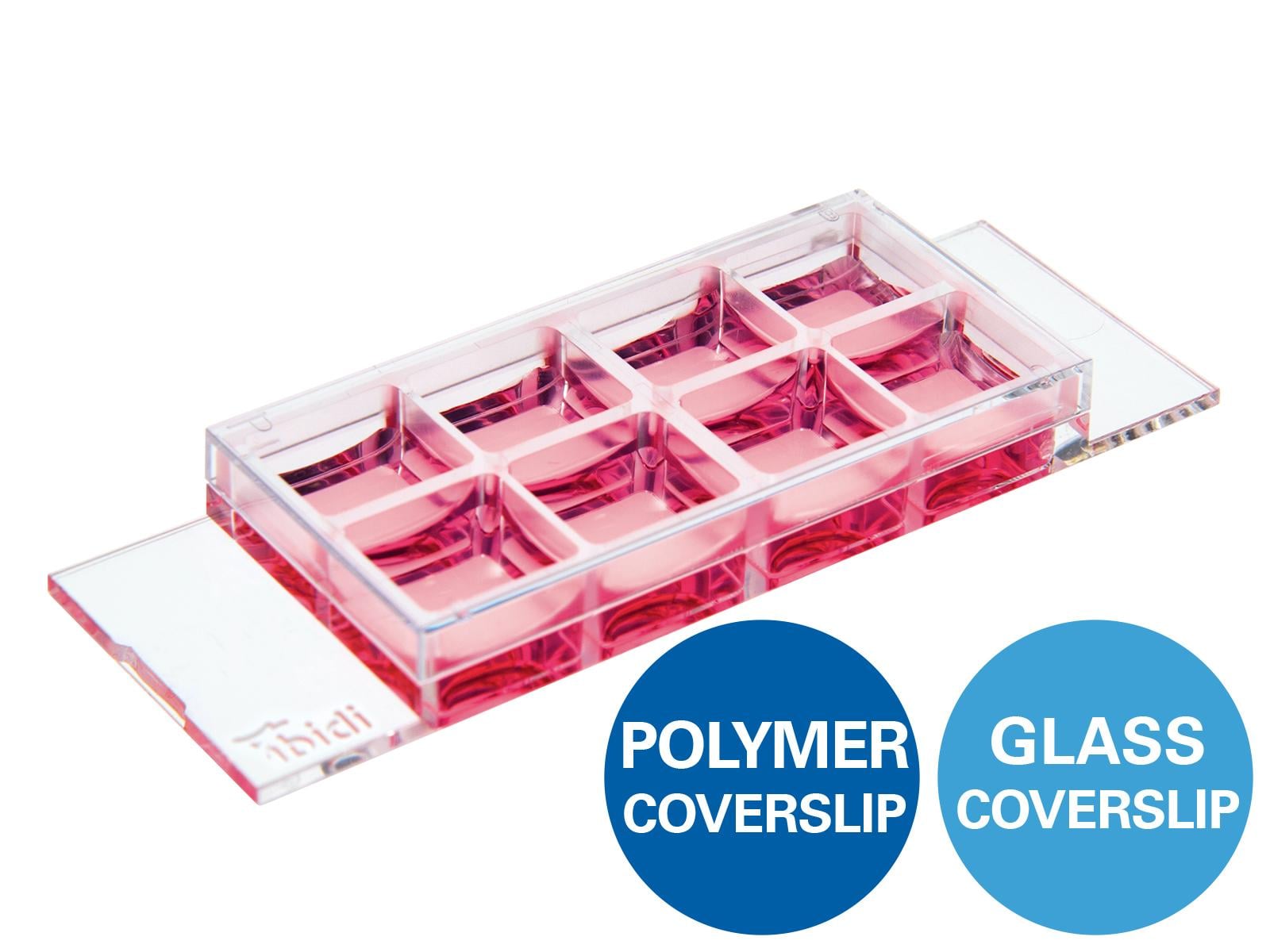
- µ-Slide 8 Well, ibiTreat, chambered coverslip (ibidi, cat.no: 80826).
- Fibronectin (100 µg/ml)
- 7-amino-4-chloromethylcoumarin (CMAC)
- Staphylococcal Enterotoxin E (SEE)
2. Equipment, Software and Settings
- Microscope NIKON TiE, 60x oil-immersion, high numerical aperture for imaging polarized traffic.
- Stage Top Incubation Chamber at 37°C, 5% CO2
- Huygens Deconvolution Software
3. Procedure
3.1 Slide Preparation to Adhere Raji Cells
- Add 150 µl of fibronectin (100 µg/ml) per well to a µ-Slide 8 Well, ibiTreat and incubate it for 30 min to 1 h at 37°C. This adhesion substrate will allow for the binding of Raji cells to the well bottom (Step 1), the formation of living conjugates with Jurkat cells (Step 4), and subsequent time-lapse microscopy (step 6). It is also compatible afterward with optional paraformaldehyde (PFA) fixation for immunofluorescence staining.
- Aspirate fibronectin using a 200 µl automatic pipette and wash each well with 200 µl of PBS for 2 min with gentle shaking. Repeat this wash one more time. The chambered coverslip can be stored at this stage with PBS for 1-2 weeks at 4°C.
3.2 Adhesion of Raji Cells to the Chambered Coverslips and 7-Amino-4-Chloromethylcoumarin (CMAC) Labeling
- Transfer 10 ml of a confluent (1-2 x 10⁶ cells/ml) pre-culture Raji cells to a 15 ml V-bottom tube. Mix well and use 10 µl to count the cells on a Neubauer chamber or equivalent.
- Centrifuge the remaining cells at 300 x g for 5 min at room temperature. Aspirate and discard the supernatant.
- Gently resuspend the cell pellet in warm complete culture medium (RPMI 1640 supplemented with 10% FCS, 2 mM glutamine, 10 mM HEPES, 100 U/ml penicillin, and 100 μg/ml streptomycin) at a concentration of 106 cells/ml.
- Label Raji cells to allow for their identification during the synaptic conjugate formation. In this experiment, 7-amino-4-chloromethylcoumarin (CMAC) labeling is performed in step 2.6.
- Transfer the required number of Raji cells in the culture medium to a 2 ml tube. For the 8 wells of the µ-Slide 8 Well, a total of 1.6 ml of the cell suspension is needed (200 µl per well).
- Add CMAC to a final concentration of 10 µM. Keep the cells in the dark by covering the tube with aluminum foil since CMAC is light-sensitive. 200 µl containing 2 x 10⁵ Raji cells are needed per 1 cm2 well. Thus, if 8 wells need to be prepared, 1.6 x 10⁶ Raji cells are required.
NOTE: Labeling Raji cells with cell tracker blue (CMAC, UV excitation, and blue emission) distinguishes them from Th cells when the synaptic conjugates are formed. This dye is compatible with PFA and acetone fixatives and allows further immunofluorescence procedures. Try to avoid light exposition. The labeling of Raji cells in a pool with CMAC followed by resuspension before the adhesion of the Raji cells to the fibronectin-coated chambered coverslips ensures the homogeneous labeling of Raji cells with CMAC among different wells.
- Resuspend CMAC-stained cells and, after aspiration of the PBS in the chambered coverslip from step 1.2., transfer 200 µl of the cell suspension to each well of the fibronectin-coated µ-Slides prepared in step 1.1-1.2. Incubate the µ-Slide at 37°C, 5% CO2 for 30 min-1 h.
NOTE: The adhesion and CMAC labeling will simultaneously occur at this step saving time. Please be aware that Raji cells will sediment quickly and caution must be taken to maintain a homogeneous concentration in the cell suspension before seeding.
Since CMAC is present in the cell suspension in large excess, the blue fluorescence background is too high to distinguish the blue-stained cells. Therefore, check cell CMAC fluorescence in step 2.7 after CMAC washing.
- Ensure that Raji cells are adhered to the bottom of the wells by shaking of the µ-Slides on the microscope. Ensure that the cells display gaps among each other and are not confluent. 50-60% of cell confluence is appropriate.
- If most of the cells efficiently adhere to the bottom of the µ-Slide and no cell gaps are observed, wash each well with warm complete medium and resuspend the medium with a 200 µl automatic pipette to detach cell excess. Check confluence after each resuspension step.
- If the cells do not adhere, repeat the adhesion step and increase adhesion time and/or cell number.
NOTE: It is possible to stop here, incubate the chambered coverslip at 37°C, 5% CO2 overnight (O/N), and continue with the protocol the next day. Then, the next day, confirm that Raji cells remain adhered and CMAC-labeled by using fluorescence microscopy.
- Rewash each well carefully with warm supplemented RPMI to eliminate excess CMAC and check for blue emission with the fluorescence microscope.
3.3 Pulse of CMAC-labeled Raji Cells with Staphylococcal Enterotoxin E
- Add Staphylococcal Enterotoxin E (SEE, 1 µg/ml) to each well. SEE can be conveniently diluted in cell culture medium (working solution at 100 µg/ml) from the SEE frozen stocks (1 mg/ml in PBS). Use 2 µl of the 100x working solution per 200 µl well volume.
CAUTION: Use gloves for this step and dispose of the used tip into the biohazard box.
- Incubate the µ-Slide at 37°C, 5% CO2 for at least 30 min. The SEE effect lasts for at least 3-4 h.
NOTE: SEE can be added to the wells at different time points when required if distinct time-lapse setups are planned (step 5).
3.4 Preparation of Jurkat Cells
- Use a previously growing culture of Jurkat cells (1-2 x 10⁶ cells/ml) for this experiment. Use cells from a standard culture flask or a previous transfection following standard electroporation protocols, as previously described (Jambrina et al., 2003). The transfection of Jurkat cells will allow for time-lapse visualization of the traffic of secretory granules in living cells. For instance, when GFP-CD63 (a marker of MVB) is expressed, the movement of GFP-CD63-decorated vesicles can be recorded (Video 1).
- Observe the cells under a phase contrast microscope. If an excess of dead cells (>20-30%) are observed, perform Ficoll density gradient centrifugation using standard protocols (Fuss et al., 2009) to eliminate the excess of dead cells (dead cells exhibit higher density than living cells) prior to use.
- Transfer the cells to a 15 ml V-bottom tube and use 10 µl for counting using a hemocytometer.
- Centrifuge the remaining cells as described in step 2.2. Discard the supernatant and resuspend the cells at the same concentration as Raji cells (1 x 10⁶/ml) using fresh, warm culture medium. Follow steps 2.2-2.3.
- Maintain the Jurkat cells in culture (37°C, 5% CO2) while waiting for step 5.
NOTE: In the second option (transfection), the number of living cells will be much lower than in the first one. Thus, consider using a higher starting cell culture volume in order to have enough cells for the experiment. From 10 x 106 Jurkat cells per electroporation cuvette and transfection, only 2-4 x 10⁶ Jurkat cells will survive after 48 h of transfection, and some of these cells will be lost during the Ficoll step.
Thus, one electroporation cuvette is generally sufficient to challenge the adhered SEE-pulsed Raji cells from 8 microwells (1.6 x 10⁶ transfected Jurkat cells needed).
3.5 Co-seeding of Raji and Jurkat Cells
- Take the µ-Slides containing the CMAC-labeled, SEE-pulsed, adhered Raji cells out of the incubator from step 3.2. It is not necessary to wash the CMAC at this stage since this was previously done in Step 2.9.
- Aspirate carefully the culture medium of each well, one by one, from one corner of the well using an automatic 200 µl pipette. Do not let the medium in the well dry out completely.
- Immediately replace the medium with 200 µl of resuspended Jurkat cells in cell culture medium (1 x 10⁶/ml) prepared in step 4.5. If performing time-lapse imaging, go to step 6 immediately after this step, since Jurkat cells tend to sediment and form synaptic conjugates very quickly. For convenience, the wells containing SEE-pulsed, adhered Raji cells that do not receive seeding with Jurkat cells at this stage should be covered with cell culture medium until they are challenged with Jurkat cells.
- If performing time-lapse imaging, add the µ-Slide to the incubation chamber and quickly proceed to step 6. This step involves the co-culture for 1-2 h in the microscope stage top incubation chamber at 37°C, 5% CO2 allowing the synaptic conjugate formation and simultaneous image acquisition.
3.6 Time-lapse Imaging of Emerging Synaptic Conjugates
- Prepare the microscope and incubation chamber prior to imaging.
NOTE: If a time-lapse experiment is planned, all the microscope settings and complements (ambient cell culture chamber, etc.) should be prepared before adding the Jurkat suspension to the chambered coverslip with adhered Raji cells.
- After Jurkat addition to each well containing the adhered Raji cells in step 5.3, quickly locate the µ-Slide on the pre-heated (1-2 hours) microscope stage incubator and select some XY positions on the microscope. Select fields in which it is likely to record an emerging IS formation made by, for instance, a Jurkat-transfected cell falling into the microscope focus.
- Use a pre-heated microscope stage incubator since it was observed that a temperature-stabilized stage maintains stable X,Y,Z positions. Criteria for a convenient XY field are: well-focused and non-confluent Raji cells (i.e., displaying gaps among cells) and the presence of transfected Jurkat cells (this can be checked by combining transmittance and UV or GFP channels). Jurkat cells will sediment very quickly (a few minutes) on the µ-Slide, and the chances to image emerging synapses will decrease with time (Video 1). Therefore, it is possible to either finish the experiment after the defined time-lapse or fix the conjugates for subsequent immunofluorescence and analyses.
NOTE: It is possible to select up to 16 different microscope fields from up to 4 different microwells for simultaneous, multi-well time-lapse acquisition with the proper temporal resolution (1-2 min per frame). The limitation relies on both the number and intensity (affecting camera exposition) of the diverse fluorochromes to be imaged (dependent on the number of expressed fluorescent proteins, apart from CMAC). One way to increase the frame rate is recording for the CMAC channel in only one out of each “n” time frames for GFP (i.e., n=8, as shown in Video 1), since Raji cells are adhered to the well bottom and do not easily move as Jurkat cells. In addition, this benefits cell viability since frequent UV light exposure may damage the cells. Try to adjust the time frame rate to 1 frame every 1 minute or less (i.e., 20 seconds per frame in Video 1, since the polarization of MVB takes a few min to hours to complete. A microscope equipped with a motorized epi-fluorescence turret and appropriate band-pass fluorescence filters or equivalents is necessary to perform this multichannel capture.
3.7 Image Processing
- Perform post-acquisition image deconvolution (i.e., Huygens deconvolution software) of time-lapse series. Deconvolute by employing an appropriate software (i.e., using the “wide field” optical option in Huygens) and the correct optical parameters. It is necessary to measure the point spread function (PSF) of the microscope (Calvo and Izquierdo, 2018) in order to apply deconvolution for image processing.
- Alternatively, use the software to calculate the idealized PSF by automatically loading the optical parameters included among the metadata from the microscope files. These optical parameters comprise fluorochrome wavelength, refraction index, numerical aperture of the objective, and the imaging technique (confocal, wide-field, etc.) (Calvo and Izquierdo, 2018).
- The imaging software uses the PSF and diverse deconvolution algorithms (i.e., QMLE and CMLE in Huygens software) in a step-by-step accumulative, calculation process, whose results then can be continuously visualized and stopped (or resumed) when required by the user. At this stage the user can change the number of convolutions and/or the signal to noise ratio and resume deconvolution. The deconvolution software works well with time-lapse series (X,Y,T) (Video 1). The deconvoluted channels were subsequently merged to the CMAC, raw channel, since cytosolic, diffuse fluorochromes do not improve by deconvolution (Calvo and Izquierdo, 2018), (Mazzeo et al., 2016).
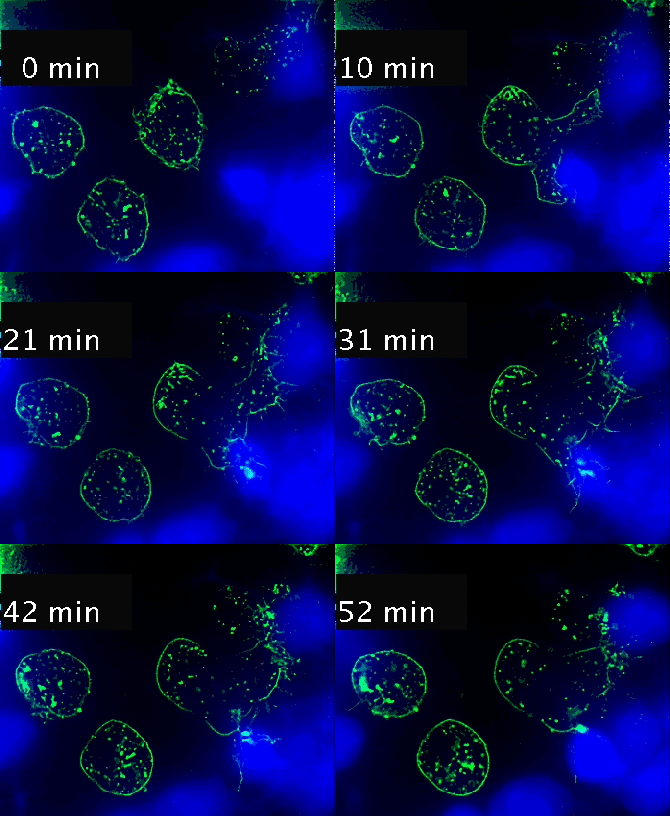
Video 1. Time-lapse imaging of immune synapse formation and multivesicular body polarization.
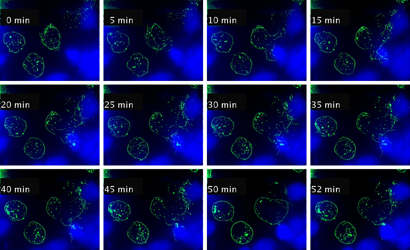
Time-lapse Montage Video 1. Immune synapse and multivesicular bodies polarization. GFP-CD63-transfected human Jurkat cells were challenged with cell tracker blue (CMAC)-labeled Raji cells (blue), that were attached to a fibronectin-coated ibidi µ-Slide 8 Well and Staphylococcal Enterotoxin E (SEE) superantigen-pulsed (30 min). Double synapse formation by one GFP-CD63-expressing Jurkat cell (center) was time-lapse imaged for 52 min by epi-fluorescence microscopy (PlanApo 60X NA 1.4). Image deconvolution was performed by using Huygens Essential (SVI, Netherlands).
The time-lapse montage shows the formation of a double synapse between the Jurkat cell and two Raji cells and the subsequent polarized traffic of multivesicular bodies (GFP-CD63-decorated vesicles) to the synaptic contact areas in the cell forming synapses (center), but not in the two Jurkat cells that do not form synapses (left). Dr. Manuel Izquierdo, IIBM Alberto Sols (CSIC-UAM). Access movie here: /img/cms/downloads/up/UP09_immune_synapse.gif
4. References
Alonso, R., Mazzeo, C., Rodriguez, M.C., Marsh, M., Fraile-Ramos, A., Calvo, V., Avila-Flores, A., Merida, I., and Izquierdo, M. (2011). Diacylglycerol kinase alpha regulates the formation and polarisation of mature multivesicular bodies involved in the secretion of Fas ligand-containing exosomes in T lymphocytes. Cell Death Differ 18, 1161-1173.
Billadeau, D.D., Nolz, J.C., and Gomez, T.S. (2007). Regulation of T-cell activation by the cytoskeleton. Nat Rev Immunol 7, 131-143.
Calvo, V., and Izquierdo, M. (2018). Imaging Polarized Secretory Traffic at the Immune Synapse in Living T Lymphocytes. Front Immunol 9, 684.
Colombo, M., Raposo, G., and Théry, C. (2014). Biogenesis, Secretion, and Intercellular Interactions of Exosomes and Other Extracellular Vesicles. Annual Review of Cell and Developmental Biology 30, 255-289.
De La Roche, M., Asano, Y., and Griffiths, G.M. (2016). Origins of the cytolytic synapse. Nat Rev Immunol 16, 421-432.
Fooksman, D.R., Vardhana, S., Vasiliver-Shamis, G., Liese, J., Blair, D.A., Waite, J., Sacristan, C., Victora, G.D., Zanin-Zhorov, A., and Dustin, M.L. (2010). Functional anatomy of T cell activation and synapse formation. Annu Rev Immunol 28, 79-105.
Fuss, I.J., Kanof, M.E., Smith, P.D., and Zola, H. (2009). Isolation of whole mononuclear cells from peripheral blood and cord blood. Curr Protoc Immunol Chapter 7, Unit 7 1.
Griffiths, G.M., Tsun, A., and Stinchcombe, J.C. (2010). The immunological synapse: a focal point for endocytosis and exocytosis. J Cell Biol 189, 399-406.
Jambrina, E., Alonso, R., Alcalde, M., Del Carmen Rodriguez, M., Serrano, A., Martinez, A.C., Garcia-Sancho, J., and Izquierdo, M. (2003). Calcium influx through receptor-operated channel induces mitochondria-triggered paraptotic cell death. J Biol Chem 278, 14134-14145.
Mazzeo, C., Calvo, V., Alonso, R., Merida, I., and Izquierdo, M. (2016). Protein kinase D1/2 is involved in the maturation of multivesicular bodies and secretion of exosomes in T and B lymphocytes. Cell Death Differ 23, 99-109.
Mittelbrunn, M., Gutierrez-Vazquez, C., Villarroya-Beltri, C., Gonzalez, S., Sanchez-Cabo, F., Gonzalez, M.A., Bernad, A., and Sanchez-Madrid, F. (2011). Unidirectional transfer of microRNA-loaded exosomes from T cells to antigen-presenting cells. Nat Commun 2, 282.
Montoya, M.C., Sancho, D., Bonello, G., Collette, Y., Langlet, C., He, H.T., Aparicio, P., Alcover, A., Olive, D., and Sanchez-Madrid, F. (2002). Role of ICAM-3 in the initial interaction of T lymphocytes and APCs. Nat Immunol 3, 159-168.
Ritter, A.T., Asano, Y., Stinchcombe, J.C., Dieckmann, N.M., Chen, B.C., Gawden-Bone, C., Van Engelenburg, S., Legant, W., Gao, L., Davidson, M.W., Betzig, E., Lippincott-Schwartz, J., and Griffiths, G.M. (2015). Actin depletion initiates events leading to granule secretion at the immunological synapse. Immunity 42, 864-876.
This User Protocol is an ibidi peer-reviewed protocol from an actual user. ibidi does not guarantee its functionality or reproducibility. For this User Protocol, ibidi provides only limited support. Please contact the corresponding author for detailed information.
For research use only.