2D/3D Flow Assay Examples: Organ-on-a-Chip & More
- Vessel-on-a-Chip Prototype
- Preclinical Bone Marrow Organ-on-a-Chip Model
- Dynamic Flow Culture of 3D Cells
- Spheroid Aggregation on a µ-Pattern Under Flow
- Phase Contrast und Fluorescence Microscopy of Pulmonary Endothelial Cells (HPMECs)
- Immunofluorescence of Flow-Conditioned Endothelial Cells
- Impedance Measurements Under Flow
- Scientific Poster: Changes in cell-cell contacts of endothelial cells (HUVEC) under long term shear stress conditions (PDF)
- Scientific Poster: Defining the Critical Shear Stress Range in Long Term HUVEC Cell Culture (PDF)
Organ-on-a-chip (OOC) systems are miniaturized microfluidic cell culture platforms that replicate key structural and functional features of human tissues. By controlling fluid flow, applying mechanical cues (e.g., shear stress or cyclic stretch), and organizing cells in physiologically relevant architectures, they enable realistic simulation of organ functions beyond conventional in vitro models.
Beyond organ-specific models such as lung, gut, or liver chips, Vessel-on-a-Chip platforms replicate the structure and function of blood vessels. By exposing endothelial cells to defined shear stress and flow conditions, they enable the study of vascular barrier function, inflammation, thrombosis, angiogenesis, and drug transport under physiologically relevant conditions.
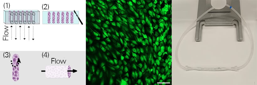
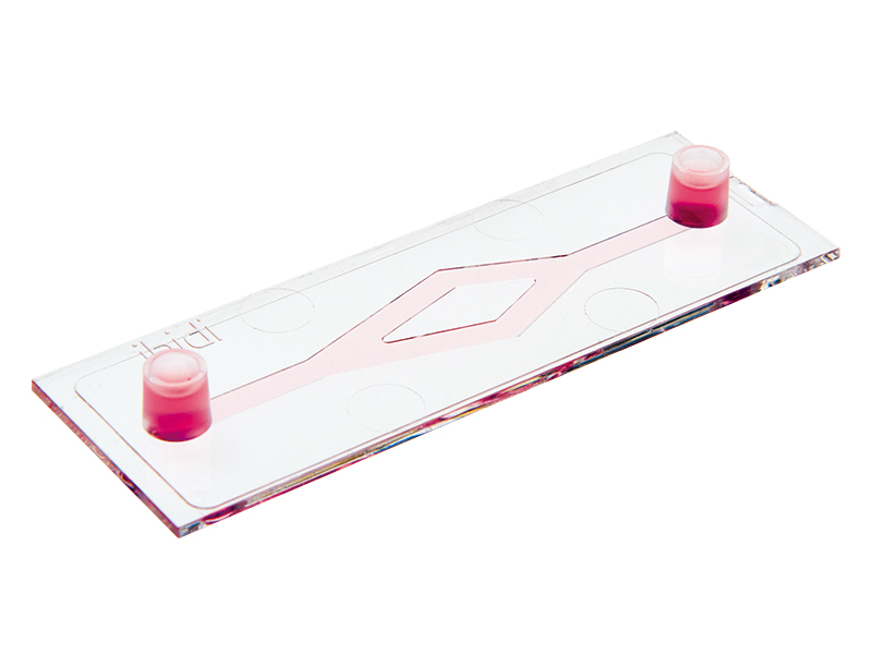
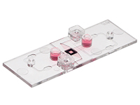
Vessel-on-a-chip prototype. Workflow schematics (left): Flexible silicone-based adhesive films were cut to match the channel geometry of a sticky-Slide VI 0.4, serving as the cell culture surface. GFP-expressing HUVEC cells were seeded into the channels on top of the adhesive films and perfused at 10 dyne/cm2 for 24 hours with the ibidi Pump System (1). After this period, the sticky-Slide VI 0.4 was removed, and the films with the HUVECs were peeled from the channels (2) and rolled into endothelial tubes (3). These tubes were connected to the perfusion tubing of the ibidi Pump System (right) and perfused (4) for additional 24 hours at 10 dyne/cm2 before imaging (middle: GFP-expressing HUVECs (green), scale bar: 100 µm). For more information, please refer to the publication here. Image courtesy of Doris Roth and Janna Nawroth, Helmholtz Pioneer Campus, Munich, Germany.
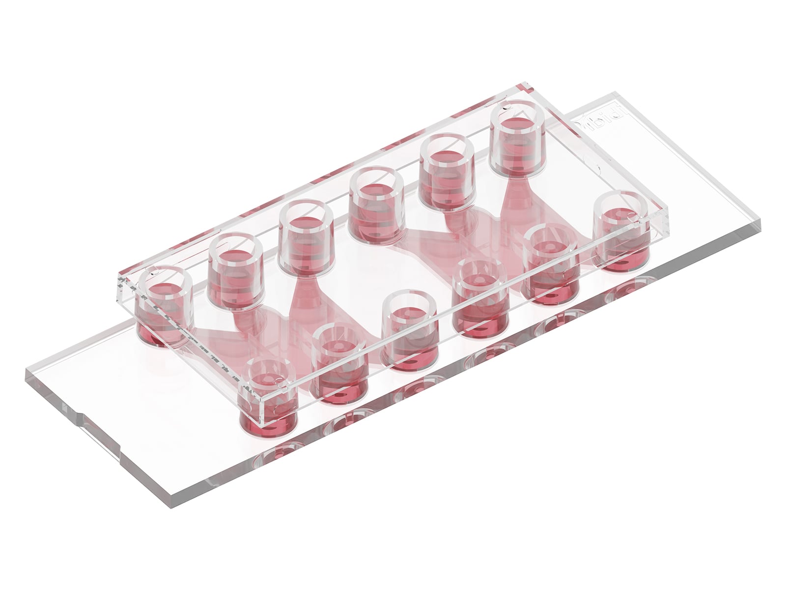
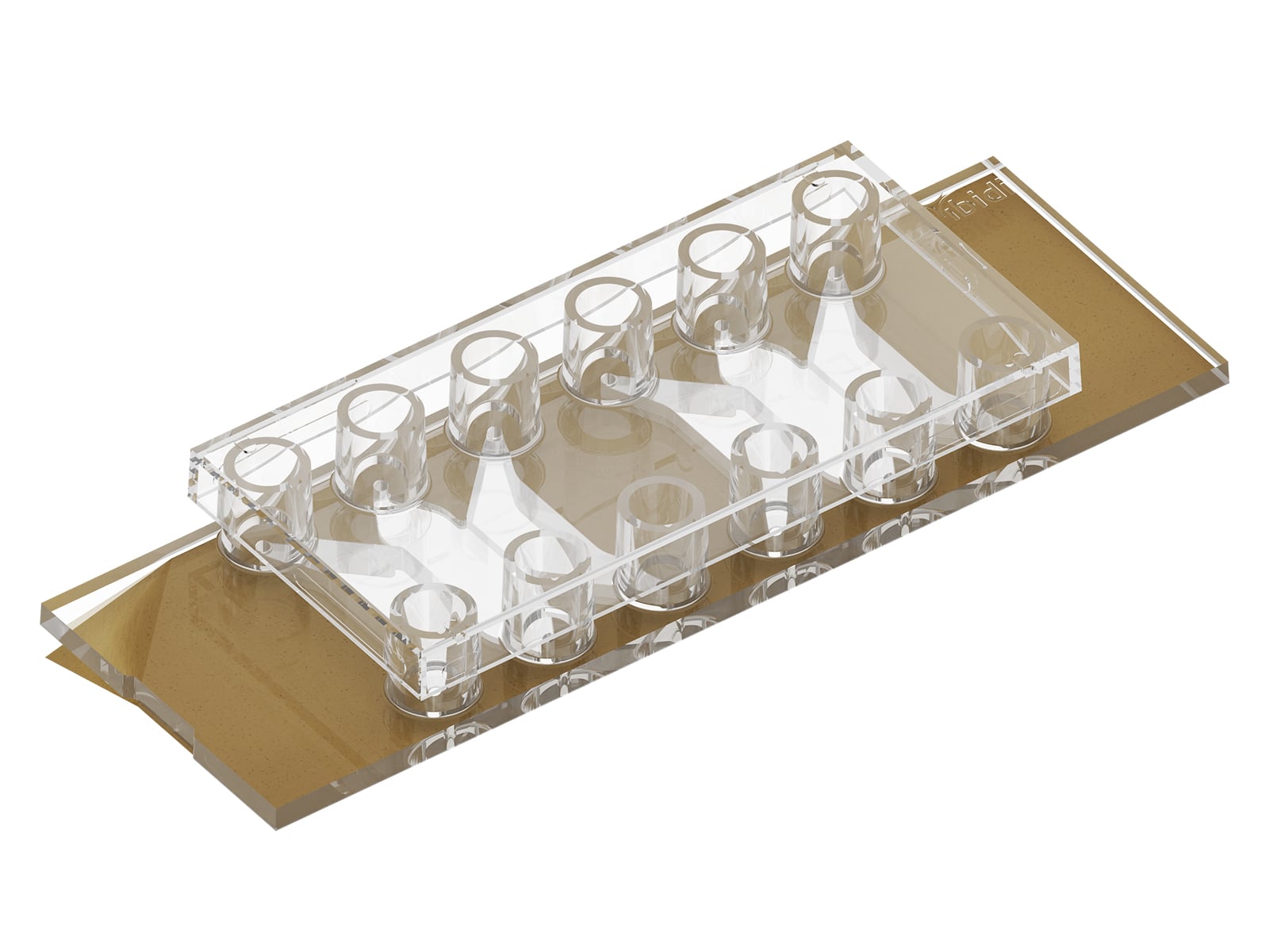
In this preclinical Organ-on-a-chip (OOC) model, iPSC-derived bone marrow organoids were cultured under defined perfusion using the ibidi Pump System and µ-Slide III 3D Perfusion. This setup enabled perfusion-based drug delivery into human bone marrow organoids, which helped reduce disease features of a chronic blood cancer called myeloproliferative neoplasm. This demonstrates the potential of dynamic microfluidic culture systems for functional therapeutic testing in patient-relevant models.
This study identified a stromal population as a key player of disease-associated niche signaling in myelofibrosis. To target this pathway, a small peptide called LSKL, was delivered through the fluidic unit under perfusion conditions. Perfusion-based LSKL treatment attenuated the myeloproliferative phenotype by specifically reducing mutant clone-derived erythropoiesis and monocytosis, while also ameliorating myelofibrosis phenotype in bone marrow organoids. The work highlights how an organ-on-a-chip platform can recapitulate complex human bone marrow niche interactions as well as supports physiologically relevant in vitro 3D models and translational studies of targeted therapies in hematologic disease.
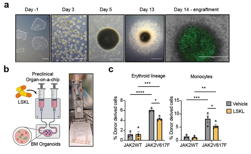
Preclinical bone marrow organ-on-a-chip model using the ibidi Pump System and µ-Slide III 3D Perfusion. (a) Representative images showing the differentiation of human iPSC-derived bone marrow organoids (Day 1-13), and exogenous donor cell engraftment for disease modeling (Day 14). Scalebars: 500 µm and 1000 µm. (b) Schematic and photograph of the perfusion-based organ-on-a-chip setup used for dynamic delivery of LSKL or vehicle control to bone marrow organoids. (c) Flow cytometry-based quantification of donor-derived erythroid lineage cells and monocytes, showing that LSKL treatment selectively reduced JAK2V617F-associated hematopoietic output compared with vehicle control. Image courtesy of Salim Atakhanov, Institute for Cell and Tumor Biology, Schneider Lab, Uniklinik RWTH Aachen, Germany. Refer to Oncodevelopmental plasticity of the skeleton in myeloid neoplasms for more information.
ibidi Solutions for Organ-on-a-Chip Applications
Dynamic Flow Culture of 3D Cells
Dynamic flow culture represents an important advancement in 3D cell culture technology. Here, spheroids, organoids or even microfabricated tissue models are continuously perfused to mimic physiological shear stress and transport. This constant flow ensures an efficient supply of nutrients and oxygen while facilitating the removal of waste products, crucial for the long-term viability and functionality of 3D cell clusters. This technique is especially valuable in drug testing, disease modeling, and tissue engineering, where accurate simulation of the in vivo environment is essential. On the downside, establishing a dynamic flow culture requires sufficient financial resources and expertise in handling.
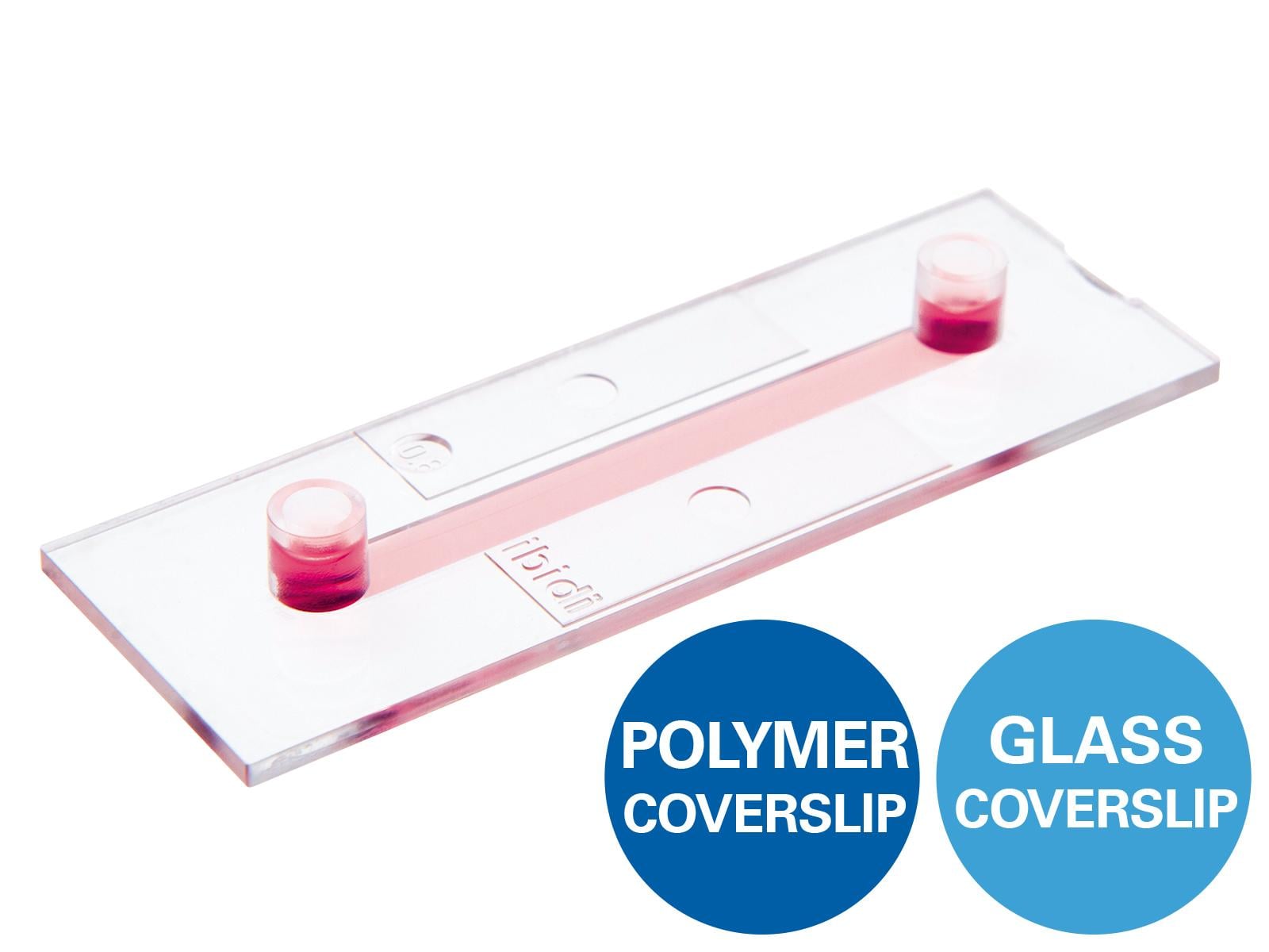
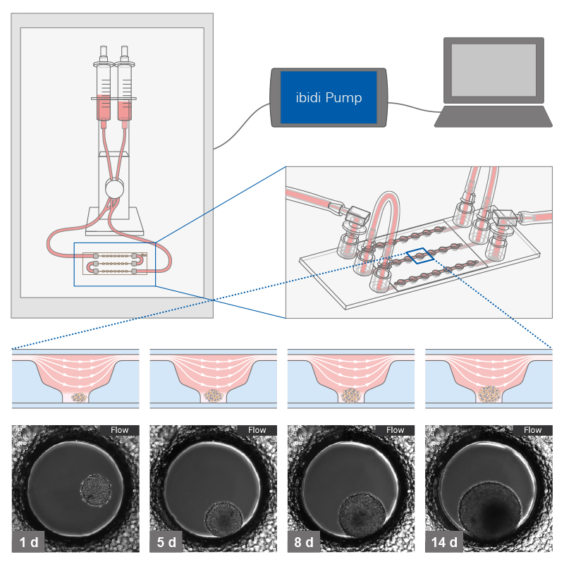
To establish a dynamic flow culture system, generated 3D structures are first seeded in a suitable microfluidic chip or culture chamber. This setup is then connected to a pump system, such as the ibidi Pump System, enabling controlled media flow. This configuration allows for the precise manipulation of flow characteristics, such as speed and pattern.
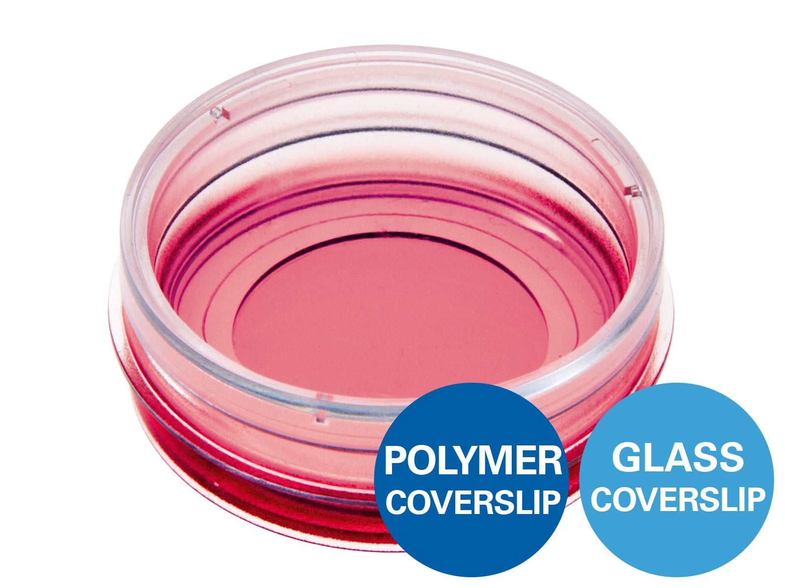
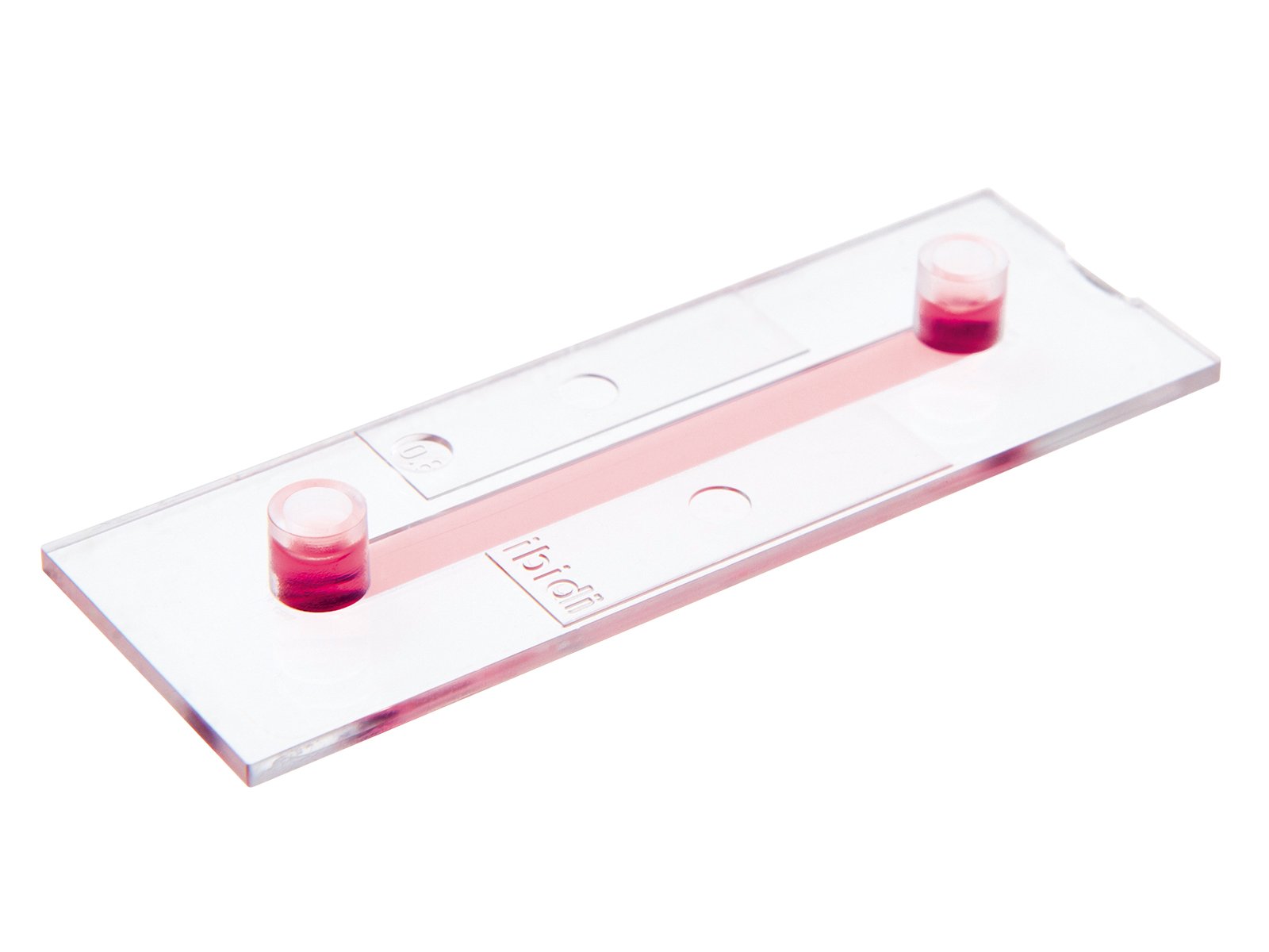
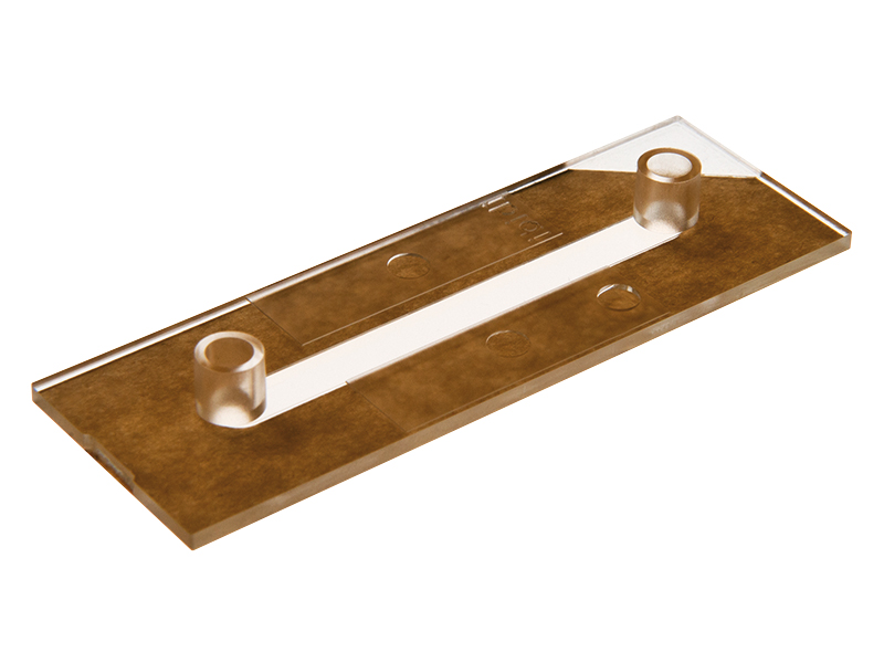
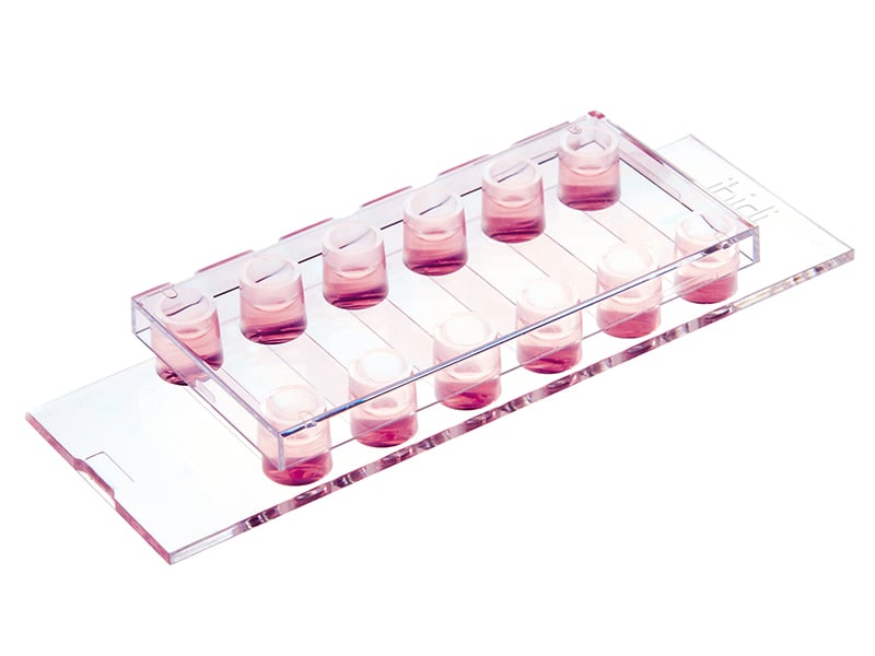
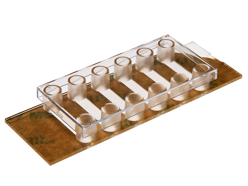
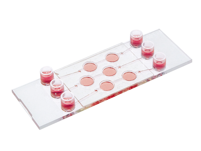
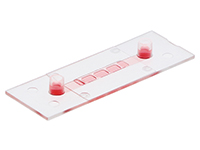
Working principle of the ibidi µ-Slide Spheroid Perfusion, which can be connected to a pump system (e.g., the ibidi Pump System) for long-term cultivation of spheroids.
L929 fibroblasts show spheroid formation in the µ-Slide Spheroid Perfusion, Bioinert, days 1–14, seeding concentration 5 x 10⁵ single cells/ml. Left: no perfusion, medium exchange every second day. Right: perfusion with the ibidi Pump System, 0.75 ml/min. Phase contrast microscopy, 10x objective lens, well diameter 800 µm.
ibidi Solutions for the Dynamic Flow Culture of 3D Cells

Spheroid Aggregation on a µ-Pattern Under Flow
The ibidi µ-Patterning technology merges adherent spots with a Bioinert surface and thus enables precise control over the spatial and dimensional properties of the aggregate growth. This structure promotes important cell-cell interactions for the formation of 3D cell aggregates. The technology's unique capability to manipulate pattern dimensions and geometries allows for the creation of spatially defined structures. Consequently, researchers can produce spheroids with consistent size, shape, and cell distribution, enhancing uniformity and experimental reproducibility.
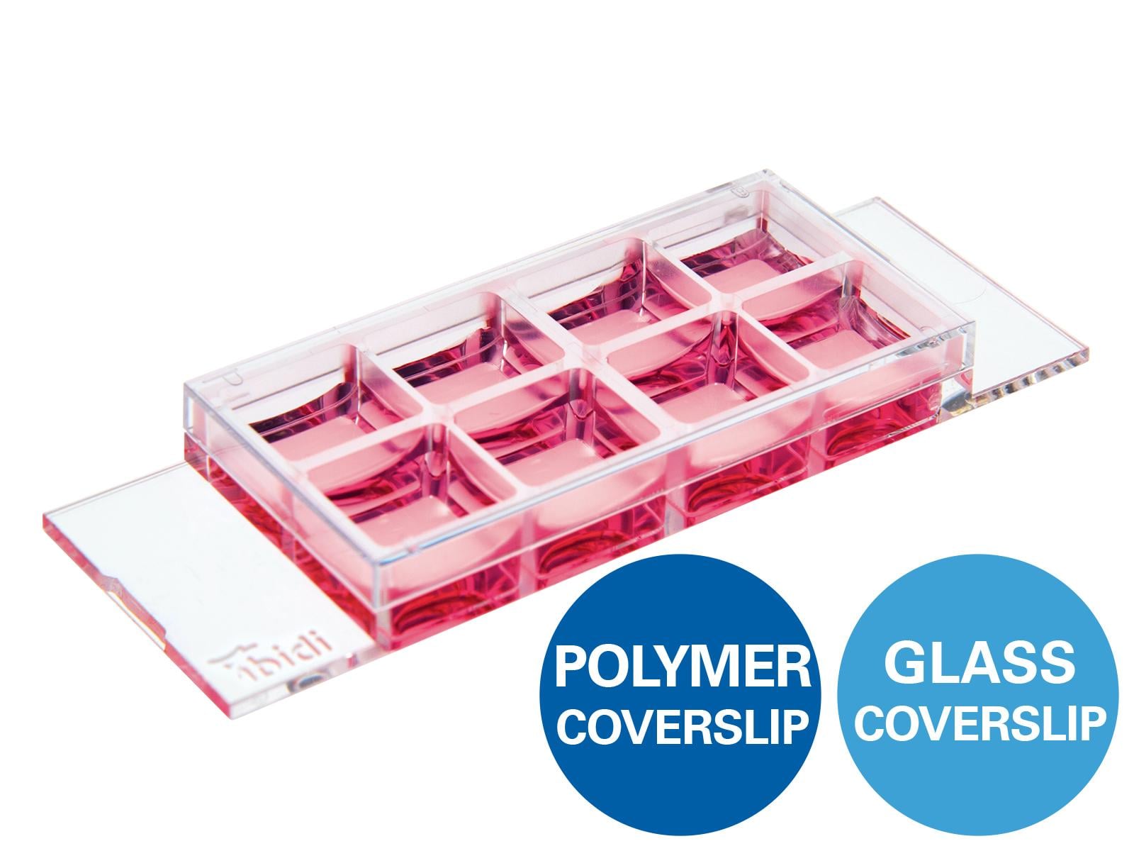
The µ-Slide VI 0.4 µ-Pattern ibiTreat, cir200, pit600, hex and the µ-Slide VI 0.4 µ-Pattern ibiTreat, cir500, pit1000, hex allow for the simultaneous generation of multiple spheroids, with a capacity of up to 200 and 75 spheroids respectively, in one channel. This translates to the potential of producing approximately 1200 and 450 spheroids respectively per µ-Slide. This feature not only increases throughput but also ensures consistency and precision in spheroid formation, crucial for advanced cell culture experiments.
Additionally, the channel design of the µ-Slide VI 0.4 is specifically engineered to accommodate integration into perfusion systems. This feature facilitates continuous media exchange and long-term cultivation, essential for creating physiological conditions that closely mimic the in vivo environment. These channels are capable of generating a defined shear stress, further improving cultivation conditions and reflecting more realistic physiological scenarios. This is central to advanced cellular studies, where maintaining and studying cells under dynamic, lifelike conditions is critical for accurate and relevant results.

3T3 fibroblasts were seeded on a patterned µ-Slide VI 0.4. A shear stress of 3 dyn/cm2 was applied 7 days after cell seeding. 15 h time lapse microscopy, 4x objective.
ibidi Solutions for Spheroid Aggregation on a µ-Pattern Under Flow
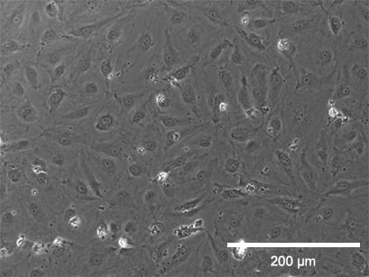
Static culture
Flow culture
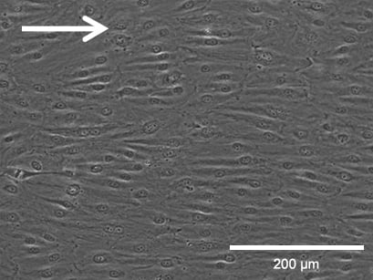

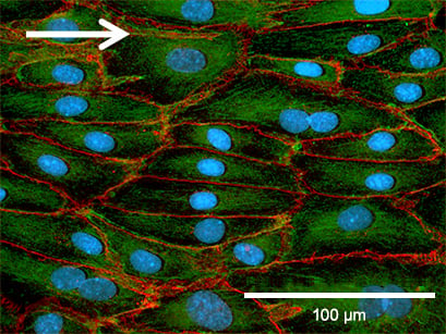
Phase contrast (top, scale bar: 200 µm) and fluorescence (bottom, scale bar: 100 µm) microscopy of HPMECs, comparing static (left) and flow culture (right) at 72h. Fluorescence labels: β-Actin (green), VE-Cadherin (red), DAPI (blue). Data by Daniel Bourquain, Robert Koch Institut, Berlin.
Immunofluorescence Staining of Flow-Conditioned Endothelial Cells
After the flow experiment, immunofluorescence stainings can easily be done in the ibidi Channel Slides. When comparing the cultivation of HUVEC under static and flow conditions, the differences in the cellular organization and various cellular compartments (e.g., tight junctions) are clearly visible.
Find detailed information about immunofluorescence staining in ibidi µ-Slides and µ-Dishes here.
Adherence Junctions (VE-Cadherin)
Under static conditions, HUVEC are generally large with a chaotically structured actin skeleton. In contrast, flow-conditioned cells are elongated and show distinct stress fibers. F-actin was stained with phalloidin (red). VE-cadherin (green), which mark the adherence junctions, are present in both conditions. Nuclei are stained using DAPI (blue).
Static culture

HUVECs were cultured at static conditions (0 dyn/cm²) for 5 days in a µ-Dish 35 mm ibiTreat. The cells were stained for VE-Cadherin (green), F-actin (red), and nuclei (blue). Imaged using a Nikon Eclipse microscope at 60x magnification.
Flow culture
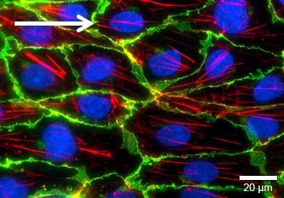
HUVECs were cultured under flow at 10 dyn/cm² for 5 days in a μ-Slide I 0.4 Luer ibiTreat. The cells were stained for VE-Cadherin (green), F-actin (red), and nuclei (blue). Imaged using a Nikon Eclipse microscope at 60x magnification.
Tight Junctions (Claudin-5)
Claudin-5, a tight junction protein, can be found at the cell-cell contact zone of flow-conditioned cells after 5 days (green). This shows that the impact of the mechanical shear stress is crucial for the differentiation of the cell layer. F-actin was stained with phalloidin (red). Nuclei are stained using DAPI (blue).
Static culture
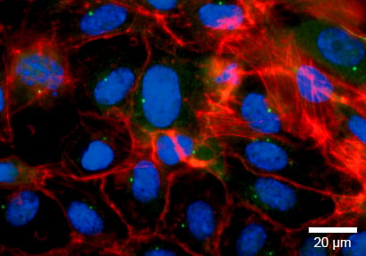
HUVECs were cultured under flow at 0 dyn/cm² for 5 days in a μ-Dish 35 mm ibiTreat. The cells were stained for claudin-5 (green), F-actin (red), and nuclei (blue). Imaged using a Nikon Eclipse microscope at 60x magnification.
Flow culture
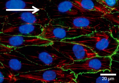
HUVECs were cultured under flow at 10 dyn/cm² for 5 days in a μ-Slide I 0.4 Luer ibiTreat. The cells were stained for claudin-5 (green), F-actin (red), and nuclei (blue). Imaged using a Nikon Eclipse microscope at 60x magnification.
Golgi Apparatus
The Golgi apparatus, stained with Anti-Human-Golgin-97 (red), is localized along the direction of flow. F-actin was stained with phalloidin (green). Nuclei are stained using DAPI (blue).
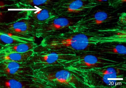
HUVECs were cultured under flow at 10 dyn/cm² for 4 days in a μ-Slide I 0.4 Luer ibiTreat. Cells were stained for Human-Golgin-97 (red), F-actin (green), and nuclei (blue). Imaged using a Nikon Eclipse microscope at 60x magnification.
Von-Willebrand-Factor
The von-Willebrand-Factor (vWF, stained with anti human von-Willebrand-Factor) is a typical endothelial cell marker. When the cells are exposed to flow, the vWF-multimers elongate to rods that are sticking to the cell membrane (green). Nuclei are stained using DAPI (blue).

HUVECs were cultured under flow at 10 dyn/cm² for 5 days in a μ-Slide I 0.4 Luer ibiTreat. The cells were stained for VE-Cadherin (green), F-actin (red), and nuclei (blue). Imaged using a Nikon Eclipse microscope at 60x magnification.
Read on and get an overview about Cell Culture Under Flow, or learn more about the Planning, Setup, and Analysis of a Flow Assay.